What is the rationale behind GPU heatsink fin design?
So I have seen a few GPU heatsinks and I wonder why some of them are how they are.
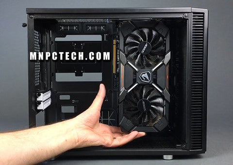
GPU placement in Cabinet
The originally intended and most widely used placement for ATX cases at least, is installing right on the PCIe slot, which goes horizontally and with the air incoming from the front of the case.

Then we have the "vertical" placement using the riser cable, which changes the direction from which the GPU fans take in air, but keep the GPU front, in the same direction, again lining up with the incoming air from the front.

Finally the very rare vertical placement, which has the front of the GPU rotated towards the top of the case, making it not line up with an airflow incoming from the front.
This also makes the GPU's ports inaccessible the standard way, giving a reason to the rarity.

Some examples I found for this

Here we see that the first 2 placements would make up most of the ATX PC builds with the third one being either for different case styles or for extensively customised builds.
Fins, fans and airflow
I would assume that having the air flow along the fins would be better than it crossing the fins at ⦜90°. And even if the air flow due to the case inlet is being ⟂ to the airflow from the GPU fans (in case of front incoming air flowing along the fins), it should still lead to overall increase in air pressure (hence, air density) between the fins.^[Source: Mental simulation] Considering that GPUs tend to have gaps in the IO shield to let the air go out the back, I would assume they (designers of the thermal dissipation solution) want air from the fins to go out the back, which would be better with fins parallel to front incoming air.

Inference and Doubt
From the above 2, it would make sense for most GPUs to have their heatsink fins going along their length instead of their width, right?
Then what's up with the ASRock lineup, with all cards other than the Passive model, the Creator cards (which have the front covered by the shroud anyway, so no incoming airflow) and the watercooled cards (which is not applicable) having the fins ⟂ to front air inlet?
And of course they are not the only one doing it that way.
Follow Up
While discussing in this thread, I realised another point (which I didn't state anywhere in the comments):
- While it is desirable to have higher air density, it is not desirable to have air increasing in density while in the inter-fin space. Because that would cause the heat released when changing density to be transferred to the fins.
- Another way to say that is, the air will get hotter, while increasing its density. So, how much this factor matters, will depend upon the initial temperature difference between the air and the fins and how long the dense air stays in the inter-fin space. Oh and also the composition of air.
The PCB too if you want to be a jackass about it
I think I saw some company advertising having specially added heat dissipation channels inside the PCB, near some hot components.
Once the PCB is heat soaked its basically useless at thermal disippation because fibreglass/resin (PCB) is an insulator. There is research being done to make micro channels into the silicon to directly water cool the chips but i doubt it will eer get to market or even be made for industry though
ceramic heat plates (or ceramic PCBs) can be used for very hot applications
Yeah, not GPUs