Hackaday
Fresh hacks every day
YOLO can mean many things, but in the context of [be_riddickulous]’s AI Talking Robot Dinosaur it refers to the “You Only Look Once” YOLOv11 object-detection algorithm by Ultralytics, the method by which this adorable dino recognizes colors and shapes to teach them to children.
If you’re new to using YOLO or object recognition more generally, [be_riddiculous]’s tutorial is not a bad place to get started. She goes through how many images you’ll need and what types to get the shape-and-color recognition needed for this project, as well as how to annotate them and train the model, either locally or in the cloud.
The project itself is an adorable paper-mache dinosaur with a servo-actuated mouth hiding some LEDs and a Raspberry Pi camera module to provide images. In operation, the dinosaur “talks” to children using pre-recorded voice lines, inviting them to play a game and put a specific shape, or shape of a specific color (or both) in its mouth. Then the aforementioned object detection (running on a laptop) goes “YOLO” and identifies the shape so the toy can provide feedback on the child’s choice via a speaker in the belly of the beast.
The link to the game code is currently not valid, but it looks like they used PyGame for the audio output code. A servo motor controls the mouth, but without that code it’s not entirely clear to us what it’s doing. We expect by the time you read this there’s good odds [be_riddickulous] will have fixed that link and you can see for yourself.
The only thing that holds this back from being a great toy to put in every Kindergarten class is the need to have a laptop close by to plug the webcam into. A Raspberry Pi 5 ought to have the horsepower to run YOLOv11, so with a little extra effort the whole thing could be standalone — there might even be room in there for batteries.We’ve had other hacks aimed at little ones, like a kid-friendly computer to relive the glory days of the school computer lab or one of the many iterations of the RFID jukebox idea. If you want to wow the kiddos with AI, perhaps take a look at this talking Santa plush.
Got a cool project, AI, kid-related, or otherwise? Don’t forget to toss us a tip!
From Blog – Hackaday via this RSS feed
If you were alive when 2001: A Space Odyssey was in theaters, you might have thought it didn’t really go far enough. After all, in 1958, the US launched its first satellite. The first US astronaut went up in 1961. Eight years later, Armstrong put a boot on the moon’s surface. That was a lot of progress for 11 years. The movie came out in 1968, so what would happen in 33 years? Turns out, not as much as you would have guessed back then. [The History Guy] takes us through a trip of what could have been if progress had marched on after those first few moon landings. You can watch the video below.
The story picks up way before NASA. Each of the US military branches felt like it should take the lead on space technology. Sputnik changed everything and spawned both ARPA and NASA. The Air Force, though, had an entire space program in development, and many of the astronauts for that program became NASA astronauts.
The Army also had its own stymied space program. They eventually decided it would be strategic to develop an Army base on the moon for about $6 billion. The base would be a large titanium cylinder buried on the moon that would house 12 people.
The base called for forty launches in a single year before sending astronauts, and then a stunning 150 Saturn V launches to supply building materials for the base. Certainly ambitious and probably overly ambitious, in retrospect.
There were other moon base plans. Most languished with little support or interest. The death knell, though, was the 1967 Outer Space Treaty, which forbids military bases on the moon.
While we’d love to visit a moon base, we are fine with it not being militarized. We also want our jet packs.
From Blog – Hackaday via this RSS feed
Most people know that they shouldn’t plug strange flash drives into their computers, but what about a USB cable? A cable doesn’t immediately register as an active electronic device to most people, but it’s entirely possible to hide a small, malicious microcontroller inside the shell of one of the plugs. [Joel Serna Moreno] and some collaborators have done just that with their Evil Crow Cable-Wind.This cable comes in two variants: one USB-A to USB-C, and one with USB-C to USB-C. A tiny circuit board containing an ESP32-S3 hides inside a USB-C plug on each cable, and can carry out a keystroke injection attack. The cable’s firmware is open-source, and has an impressive set of features: a payload syntax checker, payload autocompletion, OS detection, and the ability to impersonate the USB device of your choice.The cable provides a control interface over WiFi, and it’s possible to edit and deploy live payloads without physical access to the cable (this is where the syntax checker should be particularly useful). The firmware also provides a remote shell for computers without a network connection; the cable opens a shell on the target computer which routes commands and responses through the cable’s WiFi connection (demonstrated in the video below).The main advantage of the Evil Crow Cable Wind is its price: only about $25, at which point you can afford to lose a few during deployment. We’ve previously seen a malicious cable once before. Of course, these attacks aren’t limited to cables and USB drives; we’ve seen them in USB-C docks, in a gaming mouse, and the fear of them in fans.
Thanks to [rustysun9] for the tip!
From Blog – Hackaday via this RSS feed
During Apple’s late-90s struggles with profitability, it made a few overtures toward licensing its software to other computer manufacturers, while at the same time trying to modernize its operating system, which was threatening to slip behind Windows. While Apple eventually scrapped their licensing plans, an interesting product of the situation was Rhapsody OS. Although Apple was still building PowerPC computers, Rhapsody also had compatibility with Intel processors, which [Omores] put to good use by running it on a relatively modern i7-3770 CPU.
[Omores] selected a Gigabyte GA-Z68A-D3-B3 motherboard because it supports IDE emulation for SATA drives, a protocol which Rhapsody requires. The operating system installer needs to run from two floppy disks, one for boot and one for drivers. The Gigabyte motherboard doesn’t support a floppy disk drive, so [Omores] used an older Asus P5E motherboard with a floppy drive to install Rhapsody onto an SSD, then transferred the SSD to the Gigabyte board. The installation initially had a kernel panic during installation caused by finding too much memory available. Limiting the physical RAM available to the OS by setting the maxmem value solved this issue.
After this, the graphical installation went fairly smoothly. A serial mouse was essential here, since Rhapsody doesn’t support USB. It detected the video card immediately, and eventually worked with one of [Omores]’s ethernet cards. [Omores] also took a brief look at Rhapsody’s interface. By default, there were no graphical programs for web browsing, decompressing files, or installing programs, so some command line work was necessary to install applications. Of course, the highlight of the video was the installation of a Doom port (RhapsoDoom).
This isn’t the first obscure Apple operating system we’ve seen; some of them have even involved updates to Apple’s original releases. We’ve also seen people build Apple hardware.
Thanks to [Stephen Walters] for the tip!
From Blog – Hackaday via this RSS feed
Balancing robots are always fun to see, as they often take forms we’re not used to, such as a box standing on its corner. This project, submitted by [Alexchunlin], showcases a cool single motor reaction cube, where he dives into many lessons learned during its creation.
At the outset, [Alexchunlin] thought this would be a quick, fun weekend project, and while he achieved that, it took longer than a weekend in the end. The cube’s frame was a simple 3D print with provisions to mount his MotorGo AXIS motor controller. This motor controller was initially designed for another project, but it’s great to see him reuse it in this build.
Once the parts were printed and assembled, the real work began: figuring out the best way to keep the cube balanced on its corner. This process involved several steps. The initial control code was very coarse, simply turning the motor on and off, but this didn’t provide the fine control needed for delicate balancing. The next step was implementing a PID control loop, which yielded much better results and allowed the cube to balance on a static surface for a good amount of time. The big breakthrough came when moving from a single PID loop to two control loops. In this configuration, the PID loop made smaller adjustments, while another control loop focused on the system’s total energy, making the cube much more stable.
By the end of the build, [Alexchunlin] had a cube capable of balancing in his hand, but more importantly, it was a great learning experience in controls. Be sure to visit the project page for more details on this build and check out his video below, which shows the steps he took along the way. If you find this project interesting, be sure to explore some of our other featured reaction wheel projects.
From Blog – Hackaday via this RSS feed
Predicting the future is a dangerous occupation. Few people can claim as much success as Arthur C. Clarke, the famous science and science fiction author. Thanks to the BBC and the Australian Broadcasting Company, we can see what Sir Arthur thought about the future in 1964 and then ten years later in 1974.
Perhaps his best-known prediction was that of communication satellites, but he called quite a few other things, too. Like all prognosticators, he didn’t bat a thousand, and he missed a wrinkle or two, but overall, he has a very impressive track record.
Horizon
In the 1964 BBC show, Horizon: The Knowledge Explosion, Clarke himself talked about how hard it is to predict the future. He then goes on to describe ultra-modern cities prior to the year 2000. However, he thought that after the year 2000, we won’t care about cities. We’ll communicate with each other without regard to location. Shades of the Internet and cell phone!
He clearly saw the work-from-home revolution. However, he also thought that we’d enslave other animals, which–mercifully–didn’t come to pass. His thoughts on computers were much more on point, although we still don’t quite have what he thought we would.
Direct information dumps to your brain are probably not happening anytime soon. Suspended animation isn’t very popular, either. Of course, all of this could still happen, and it would be totally spooky if he’d been 100% right.
To wrap up, he talks about a replicator when K. Eric Drexler was not even ten years old. We won’t say he called out the 3D printer, exactly, but he was on the track.
The Home Computer
Fast forward to 1974. A science reporter brought his son with him to an old-school mainframe room and pointed out to Clarke that in the year 2001, the boy would be an adult. Clarke predicted that the boy would have a computer in his house that would connect to other computers to get all the information he needed.
Once again, Clarke was really interested in being able to work from anywhere in the world. Of course, he moved to Sri Lanka and still managed to work, so maybe he just thought we should all enjoy the same privilege.
Two Years Later
In 1976, Clarke spoke with an AT&T interviewer about the future. He clearly saw the Internet for news and communications with — you guessed it — working from home.
He also brought up the smart watch, another invention to add to his yes column. About the only thing in that interview that we haven’t had luck with yet is contact with extraterrestrials.
Our Guess
We try not to make too many predictions. But we are going to guess that at least some of Clarke’s predictions are yet to come. There is one thing we are pretty sure of, though. When anyone predicts the future — even Clarke — they rarely see the gritty details. Sure, he saw the cell phone, but not the cell phone plan. Or malware. Or a host of other modern problems that would perplex anyone back in the 1960s.
Clarke has a better track record than most. We love looking at what people thought we’d be doing here in the future.
From Blog – Hackaday via this RSS feed
It is a well-known reality of rescuing certain older electronic devices that, at some point, you’re likely going to have to replace a busted capacitor. This is the stage [Kevin] is at in the 3rd installment in his saga of reviving a 50-year-old Military Tektronix oscilloscope.
[Kevin] recently discovered a failed capacitor in the power supply for this vintage analog scope. Having identified and removed the culprit, it was time to find a way to replace the faulty component with a modern equivalent. The original capacitor is out of fashion to the degree that a perfect replacement would be impractical and likely not desirable. This job would call for a bit of adaptation.
Starting with the recently desoldered pads on the power supply board as a template, [Kevin] walks us through his process of transferring his meticulously acquired measurements to KiCAD for the purpose of creating an adapter PCB. Once the original pads are mapped, he then draws in pads matching the leads of the new component, referencing the manufacturer’s schematic of the replacement part.
With everything drawn in place and design rule checks satisfied, it’s a quick turnaround from the PCB fabricator before this Tektronix scope moves one step closer to happy tracing again.
While the end product of this kludge is about as simple of a PCB as you might imagine, [Kevin’s] documentation is a thorough tutorial on the process for retrofitting components via adapter boards, covering some of the subtleties that you might miss if you’ve never been through it before.
We are looking forward to the next installment of Kevin’s undertaking. In the meantime, you can delve into other oscilloscope repair projects, here, here and here, or go deep on why capacitors fail as in the capacitor plague of the early 2000s (though these are not the same vintage or necessarily the same reason for failure as in [ Kevin’s ] device).
From Blog – Hackaday via this RSS feed
If you’re a mechanical engineering wonk, you might appreciate this latest video from [Henry Segerman] wherein he demonstrates his various expanding racks.
[Henry] explains how the basic “double-rack” unit can be combined to make more complex structures. These structures are similar in spirit to the Hoberman sphere, which is a compact structure that can be expanded to fill a large space.
The double-rack units get a lot more interesting when you combine two or more of them. They each have rails that accommodate additional double-racks, holding the double-racks together. Because of how the gears from each double-rack are connected to the teeth of the others, expanding two double-racks causes all connected units to also expand.
Through the rest of the video, [Henry] shows you the marvelous myriad ways the basic structures can be combined to make remarkable expanding racks. He also explains some of the missteps and gotchas that his latest designs avoid based on his experience.
If you’re interested in such things, you might also like to check out Lathe Gears Make A Clock or Gear Up: A 15-Minute Intro On Involute Gears.
Do you have your own mechanical engineering hacks? Let us know on the tips line!
From Blog – Hackaday via this RSS feed
It’s never a bad time to look at a clock, and one could certainly do worse than this delightful Paper Sunshine Clock by [anneosaur]. The sun-ray display is an interesting take on the analog clock, and its method of operation is not one we see every day, either.
Reading the clock is straightforward: there are twelve rays divided into two segments. Once you figure out that this artful object is a clock, it’s easy enough to guess that the rays give the hours, and half-rays are half-hours. In the photo above, it’s sometime between nine o’clock and nine thirty. Our Swiss readers might not be terribly impressed, but a “fuzzy” clock like this is quite good enough much of the time for many people.
Even the flex PCB holding the resistors looks like a work of art.
The title gives away its method of operation: it’s thermochromic paint! The paint is printed onto a piece of Japanese awagami paper, which is pressed against a flexible PCB holding an array of resistors. Large copper pads act as heat spreaders for the resistors. For timekeeping and control, an Atmega328PB is paired with a DS3231MZ RTC, with a coin cell for backup power when the unit is unplugged. (When plugged in, the unit uses USB-C, as all things should.) That’s probably overkill for a +/-30 minute display, but we’re not complaining.
The Atmega328PB does not have quite enough outputs to drive all those resistors, so a multiplexing circuit is used to let the 10 available GIPO control current to 24 rays. Everything is fused for safety, and [anneosaur] even includes a temperature sensor on the control board. The resistors are driven by a temperature-compensated PWM signal to keep them from overheating or warming up too slowly, regardless of room temperature. The attention to detail here is as impressive as the aesthetics.
[annenosaur] has even thought of those poor people for whom such a fuzzy clock would never do (be they Swiss or otherwise) — the Paper Sunshine Clock has a lovely “sparkle mode” that turns the rays on and off at random, turning the clock into an art piece. A demo video of that is below. If you find this clock to be a ray of sunshine, everything you need to reproduce it is on GitHub under an MIT or CC4.0 license.
This is not the first thermochromic clock we’ve featured, though the last one was numeric. If you must have minute accuracy in a thermochromic analog clock, we’ve got you covered there, too.
Special thanks to [anneosaur] for submitting the hack. If you’ve seen (or made) a neat clock, let us know! You won’t catch us at a bad time; it’s always clock time at Hackaday.
From Blog – Hackaday via this RSS feed
For a world covered in oceans, getting a drink of water on Planet Earth can be surprisingly tricky. Fresh water is hard to come by even on our water world, so much so that most sources are better measured in parts per million than percentages; add together every freshwater lake, river, and stream in the world, and you’d be looking at a mere 0.0066% of all the water on Earth.
Of course, what that really says is that our endowment of saltwater is truly staggering. We have over 1.3 billion cubic kilometers of the stuff, most of it easily accessible to the billion or so people who live within 10 kilometers of a coastline. Untreated, though, saltwater isn’t of much direct use to humans, since we, our domestic animals, and pretty much all our crops thirst only for water a hundred times less saline than seawater.
While nature solved the problem of desalination a long time ago, the natural water cycle turns seawater into freshwater at too slow a pace or in the wrong locations for our needs. While there are simple methods for getting the salt out of seawater, such as distillation, processing seawater on a scale that can provide even a medium-sized city with a steady source of potable water is definitely a job for Big Chemistry.
Biology Backwards
Understanding an industrial chemistry process often starts with a look at the feedstock, so what exactly is seawater? It seems pretty obvious, but seawater is actually a fairly complex solution that varies widely in composition. Seawater averages about 3.5% salinity, which means there are 35 grams of dissolved salts in every liter. The primary salt is sodium chloride, with potassium, magnesium, and calcium salts each making a tiny contribution to the overall salinity. But for purposes of acting as a feedstock for desalination, seawater can be considered a simple sodium chloride solution where sodium anions and chloride cations are almost completely dissociated. The goal of desalination is to remove those ions, leaving nothing but water behind.
While thermal desalination methods, such as distillation, are possible, they tend not to scale well to industrial levels. Thermal methods have their place, though, especially for shipboard potable water production and in cases where fuel is abundant or solar energy can be employed to heat the seawater directly. However, in most cases, industrial desalination is typically accomplished through reverse osmosis RO, which is the focus of this discussion.
In biological systems, osmosis is the process by which cells maintain equilibrium in terms of concentration of solutes relative to the environment. The classic example is red blood cells, which if placed in distilled water will quickly burst. That’s because water from the environment, which has a low concentration of solutes, rushes across the semi-permeable cell membrane in an attempt to dilute the solutes inside the cell. All that water rushing into the cell swells it until the membrane can’t take the pressure, resulting in hemolysis. Conversely, a blood cell dropped into a concentrated salt solution will shrink and wrinkle, or crenellate, as the water inside rushes out to dilute the outside environment.
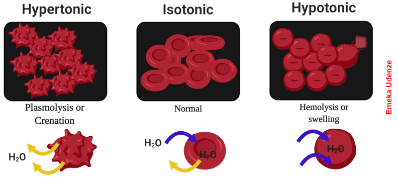
Water rushes in, water rushes out. Either way, osmosis is bad news for red blood cells. Reversing the natural osmotic flow of a solution like seawater is the key to desalination by reverse osmosis. Source: Emekadecatalyst, CC BY-SA 4.0.
Reverse osmosis is the opposite process. Rather than water naturally following a concentration gradient to equilibrium, reverse osmosis applies energy in the form of pressure to force the water molecules in a saline solution through a semipermeable membrane, leaving behind as many of the salts as possible. What exactly happens at the membrane to sort out the salt from the water is really the story, and as it turns out, we’re still not completely clear how reverse osmosis works, even though we’ve been using it to process seawater since the 1950s.
Battling Models
Up until the early 2020s, the predominant model for how reverse osmosis (RO) worked was called the “solution-diffusion” model. The SD model treated RO membranes as effectively solid barriers through which water molecules could only pass by first diffusing into the membrane from the side with the higher solute concentration. Once inside the membrane, water molecules would continue through to the other side, the permeate side, driven by a concentration gradient within the membrane. This model had several problems, but the math worked well enough to allow the construction of large-scale seawater RO plants.
The new model is called the “solution-friction” model, and it better describes what’s going on inside the membrane. Rather than seeing the membrane as a solid barrier, the SF model considers the concentrate and permeate surfaces of the membrane to communicate through a series of interconnected pores. Water is driven across the membrane not by concentration but by a pressure gradient, which drives clusters of water molecules through the pores. The friction of these clusters against the walls of the pores results in a linear pressure drop across the membrane, an effect that can be measured in the lab and for which the older SD model has no explanation.
As for the solutes in a saline solution, the SF model accounts for their exclusion from the permeate by a combination of steric hindrance (the solutes just can’t fit through the pores), the Donnan effect (which says that ions with the opposite charge of the membrane will get stuck inside it), and dielectric exclusion (the membrane presents an energy barrier that makes it hard for ions to enter it). The net result of these effects is that ions tend to get left on one side of the membrane, while water molecules can squeeze through more easily to the permeate side.
Turning these models into a practical industrial process takes a great deal of engineering. A seawater reverse osmosis or SWRO, plant obviously needs to be located close to the shore, but also needs to be close to supporting infrastructure such as a municipal water system to accept the finished product. SWRO plants also use a lot of energy, so ready access to the electrical grid is a must, as is access to shipping for the chemicals needed for pre- and post-treatment.
Pores and Pressure
Seawater processing starts with water intake. Some SWRO plants use open intakes located some distance out from the shoreline, well below the lowest possible tides and far from any potential source of contamination or damage, such a ship anchorages. Open intakes generally have grates over them to exclude large marine life and debris from entering the system. Other SWRO plants use beach well intakes, with shafts dug into the beach that extend below the water table. Seawater filters through the sand and fills the well; from there, the water is pumped into the plant. Beach wells have the advantage of using the beach sand as a natural filter for particulates and smaller sea critters, but do tend to have a lower capacity than open intakes.
Aside from the salts, seawater has plenty of other unwanted bits, all of which need to come out prior to reverse osmosis. Trash racks remove any shells, sea life, or litter that manage to get through the intakes, and sand bed filters are often used to remove smaller particulates. Ultrafiltration can be used to further clarify the seawater, and chemicals such as mild acids or bases are often used to dissolve inorganic scale and biofilms. Surfactants are often added to the feedstock, too, to break up heavy organic materials.
By the time pretreatment is complete, the seawater is remarkably free from suspended particulates and silt. Pretreatment aims to reduce the turbidity of the feedstock to less than 0.5 NTUs, or nephelometric turbidity units. For context, the US Environmental Protection Agency standard for drinking water is 0.3 NTUs for 95% of the samples taken in a month. So the pretreated seawater is almost as clear as drinking water before it goes to reverse osmosis.
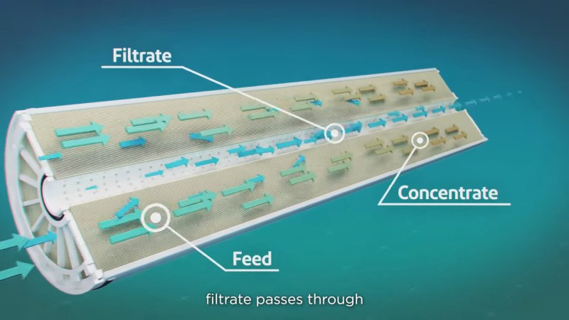
SWRO cartridges have membranes wound into spirals and housed in pressure vessels. Seawater under high pressure enters the membrane spiral; water molecules migrate across the membrane to a center permeate tube, leaving a reject brine that’s about twice as saline as the feedstock. Source: DuPont Water Solutions.
The heart of reverse osmosis is the membrane, and a lot of engineering goes into it. Modern RO membranes are triple-layer thin-film composites that start with a non-woven polyester support, a felt-like material that provides the mechanical strength to withstand the extreme pressures of reverse osmosis. Next comes a porous support layer, a 50 μm-thick layer of polysulfone cast directly onto the backing layer. This layer adds to the physical strength of the backing and provides a strong yet porous foundation for the active layer, a cross-linked polyamide layer about 100 to 200 nm thick. This layer is formed by interfacial polymerization, where a thin layer of liquid monomer and initiators is poured onto the polysulfone to polymerize in place.
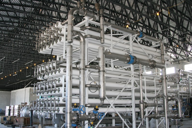
An RO rack in a modern SWRO desalination plant. Each of the white tubes is a pressure vessel containing seven or eight RO membrane cartridges. The vessels are plumbed in parallel to increase flow through the system. Credit: Elvis Santana, via Adobe Stock.
Modern membranes can flow about 35 liters per square meter every hour, which means an SWRO plant needs to cram a lot of surface area into a little space. This is accomplished by rolling the membrane up into a spiral and inserting it into a fiberglass pressure vessel, which holds seven or eight cartridges. Seawater pumped into the vessel soaks into the backing layer to the active layer, where only the water molecules pass through and into a collection pipe at the center of the roll. The desalinated water, or permeate, exits the cartridge through the center pipe while rejected brine exits at the other end of the pressure vessel.
The pressure needed for SWRO is enormous. The natural osmotic pressure of seawater is about 27 bar (27,000 kPa), which is the pressure needed to halt the natural flow of water across a semipermeable membrane. SWRO systems must pressurize the water to at least that much plus a net driving pressure (NPD) to overcome mechanical resistance to flow through the membrane, which amounts to an additional 30 to 40 bar.
Energy Recovery
To achieve these tremendous pressures, SWRO plants use multistage centrifugal pumps driven by large, powerful electric motors, often 300 horsepower or more for large systems. The electricity needed to run those motors accounts for 60 to 80 percent of the energy costs of the typical SWRO plant, so a lot of effort is put into recovering that energy, most of which is still locked up in the high-pressure rejected brine as hydraulic energy. This energy used to be extracted by Pelton-style turbines connected to the shaft of the main pressure pump; the high-pressure brine would spin the pump shaft and reduce the mechanical load on the pump, which would reduce the electrical load. Later, the brine’s energy would be recovered by a separate turbo pump, which would boost the pressure of the feed water before it entered the main pump.
While both of these methods were capable of recovering a large percentage of the input energy, they were mechanically complex. Modern SWRO plants have mostly moved to isobaric energy recovery devices, which are mechanically simpler and require much less maintenance. Isobaric ERDs have a single moving part, a cylindrical ceramic rotor. The rotor has a series of axial holes, a little like the cylinder of an old six-shooter revolver. The rotor is inside a cylindrical housing with endcaps on each end, each with an inlet and an outlet fitting. High-pressure reject brine enters the ERD on one side while low-pressure seawater enters on the other side. The slugs of water fill the same bore in the rotor and equalize at the same pressure without much mixing thanks to the different densities of the fluids. The rotor rotates thanks to the momentum carried by the incoming water streams and inlet fittings that are slightly angled relative to the axis of the bore. When the rotor lines up with the outlet fittings in each end cap, the feed water and the brine both exit the rotor, with the feed water at a higher pressure thanks to the energy of the reject brine.
For something with only one moving part, isobaric ERDs are remarkably effective. They can extract about 98% of the energy in the reject brine, pressuring the feed water about 60% of the total needed. An SWRO plant with ERDs typically uses 5 to 6 kWh to produce a cubic meter of desalinated water; ERDs can slash that to just 2 to 3 kWh.
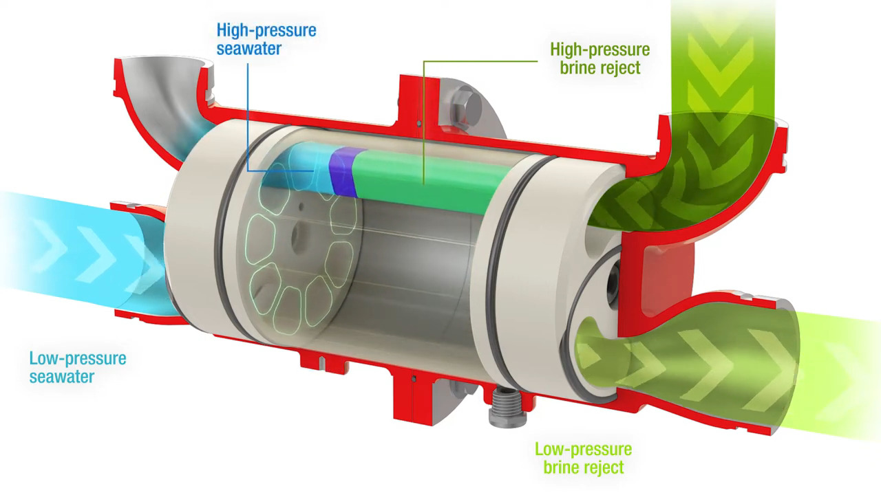
Isobaric energy recovery devices can recover half of the electricity used by the typical SWRO plant by using the pressure of the reject brine to pressurize the feed water. Source: Flowserve.
Finishing Up
Once the rejected brine’s energy has been recovered, it needs to be disposed of properly. This is generally done by pumping it back out into the ocean through a pipe buried in the seafloor. The outlet is located a considerable distance from the inlet and away from any ecologically sensitive areas. The brine outlet is also generally fitted with a venturi induction head, which entrains seawater from around the outlet to partially dilute the brine.
As for the permeate that comes off the RO racks, while it is almost completely desalinated and very clean, it’s still not suitable for distribution into the drinking water system. Water this clean is highly corrosive to plumbing fixtures and has an unpleasantly flat taste. To correct this, RO water is post-processed by passing it over beds of limestone chips. The RO water tends to be slightly acidic thanks to dissolved CO2, so it partially dissolves the calcium carbonate in the limestone. This raises the pH closer to neutral and adds calcium ions to the water, which increases its hardness a bit. The water also gets a final disinfection with chlorine before being released to the distribution network.
From Blog – Hackaday via this RSS feed
As useful as corrugated cardboard is, we generally don’t consider it to be a very sturdy material. The moment it’s exposed to moisture, it begins to fall apart, and it’s easily damaged even when kept dry. That said, there are ways to make corrugated cardboard a lot more durable, as demonstrated by the [NightHawkInLight]. Gluing multiple panels together so that the corrugation alternates by 90 degrees every other panel makes them more sturdy, with wheat paste (1:5 mixture of flour and water) recommended as adhesive.
More after the break…
Other tricks are folding over edges help to protect against damage, and integrating wood supports. Normal woodworking tools like saws can cut these glued-together panels. Adding the wheat paste to external surfaces can also protect against damage. By applying kindergarten papier-mâché skills, a custom outside layer can be made that can be sanded and painted for making furniture, etc.
Beyond these and other tips, there remains the issue of protection against water intrusion. The (biodegradable) solution here is shellac. Unfortunately, pure (canned) shellac isn’t good enough for long-term exposure to moisture, so the recipe recommended here is: 0.5 L of (~91%) IPA, 125 g of shellac flakes, and 15 g of beeswax. After heating and stirring, a paste wax is created that can be brushed on the cardboard to provide water resistance, without turning said cardboard into chemical waste.
As an alternative waterproof coating (but not biodegradable) there’s another recipe: 100 g hot glue sticks, 25 g paraffine wax or beeswax, and 20 mL of mineral oil (which lowers the melting temperature).
Although these methods, including the also discussed UV protection coatings – require some time and materials investment. Since cardboard is effectively free, there’s something to be said for this approach, if only as a fun chemistry or physics project. For [NightHawkInLight] it’s being used as the roof on his DIY camper, for which it seems like a nice lightweight, waterproof option.
Thanks to [James Newton] for the tip.
From Blog – Hackaday via this RSS feed
[Doug Brown] had a problem. He uses a dummy HDMI plug to fool a computer into thinking it has a monitor for when you want to run the computer headless. The dummy plug is a cheap device that fools the computer into thinking it has a monitor and, as such, has to send the Extended Display ID (EDID) to the computer. However, that means the plug pretends to be some kind of monitor. But what if you want it to pretend to be a different monitor?
The EDID is sent via I2C and, as you might expect, you can use the bus to reprogram the EEPROM on the dummy plug. [Doug] points out that you can easily get into trouble if you do this with, for example, a real monitor or if you pick the wrong I2C bus. So be careful.
In [Doug’s] case, he wanted to drop a 4K dummy plug to 1080p, but you could probably just as easily go the other way. After all, the plug itself couldn’t care less what kind of video you send it. It drops it all anyway.
Want to know more about HDMI? We can help out with that.
From Blog – Hackaday via this RSS feed
XR may not have crashed into our lives as much as some tech billionaires have wished, but that doesn’t stop the appeal of a full display that takes up no physical space. At that point, why not get rid of the computer that takes up living space as well? That is what [Michael] tries to do with Bento, the form factor of an Apple Magic keyboard and the power of a Steam Deck.
Steam Deck modding is a great project to get started on but we don’t see too many VR or XR uses of the mobile pc. While the VR gaming potential is limited by lackluster power, general productivity is a perfect use case. All that productivity power can be found in a 3D printed case with a battery, allowing for some mobile use. A magic keyboard sits on top of the case, so the entire package takes up less space than the average mechanical keyboard. However, we could always support the addition of a mechanical key version. There’s plenty of spare room in this current design, just look at the storage area!
[Michael] believes that this use of XR fulfills a more true course for “spatial computing” than Apple’s Vision Pro. Of course, this design is not restricted to only XR use; the Steam Deck is capable of running on any normal monitor you would like. Regardless, we need to see the model files to verify for ourselves! [Michael] claims these resources will be available soon, and trust us that we will be waiting!
Minimalist builds are far from unheard of here on Hackaday. After all, less room taken up by random cables or clutter means more room for projects. This is a lesson clearly followed by similar projects such as this completely wireless-powered desktop!
From Blog – Hackaday via this RSS feed
Many FDM filament dryers have a port through which you can guide the filament. This handy feature allows you to print from the spool without removing it from the dryer, saving time and limiting exposure to (moist) air. Unfortunately, these exit ports aren’t always thought out very well, mostly in terms of the angle with the spool as it unrolls. The resulting highly oblique orientation means a lot of friction of the filament on the side of the port. This issue is addressed in a recent [Teaching Tech] video, with a simple, low-cost solution.
The basic idea is to have a swiveling port, inspired by a spherical bearing. The design shown in the video uses a PC4-M6 pneumatic connector to pass the PTFE tube. Connector choice is critical here, as many PC4-M6 pneumatic connectors won’t accommodate the PTFE. As a fallback, you can drill out a connector to enable this.
Once the connector is sorted, you need a 13 mm (~0.5″) step drill bit to widen the opening in the filament dryer. This ready-to-print version has 10 degrees of freedom in any direction, but you can adapt it to fit your needs. With this mod installed, the angle with which the filament enters the port should remain as close to zero as possible, preventing both friction and damage to the port and filament.
From Blog – Hackaday via this RSS feed
If William Gibson and Bruce Sterling had written an arcade scene into “The Difference Engine”, it probably would have looked a lot like [Pete Wood]’s Meccano Martian Mission, as illustrated in the video below by the [London Meccano Club]. Meccano Martian Mission is an homage to Atari’s 1978 Lunar Lander video game, but entirely electromechanical and made of– you guessed it– Meccano.
You might think Meccano is “too modern” to count as steampunk, but it squeaks just into the Victorian era. The first sets hit stores in 1901, the last year of Queen Victoria’s long reign. Since then, Meccano has developed a large following that has produced some truly impressive constructions, and this arcade game can stand amongst the best of them.
The game has all the features of the original: a swiveling spaceship, two-axis speed control, and even a little yellow flame that pops out when you are applying thrust. There’s a timer and a fuel gauge, and just like the original, there are easier and harder landing pads that offer score multipliers. While the score must be totted up manually, the game will detect a crash and flag it with a pop-down banner. It really has to be seen to be believed. It’s all done with cams and differentials hitting potentiometers and microswitches — not an Arduino in sight; [Pete] does a good job explaining it in the second half of the embedded video, starting about 10 minutes in.
The brains of the operation: cams and gears, and ingenuity.
Sure, might not be new or groundbreaking — these are old, old techniques — but not many people know them well enough to use them anymore, especially not with this degree of sophistication. To see these electromechanical techniques applied anachronistically to replicate one of the great pioneers of the arcade world tickles our fancy. It’s no wonder that perfecting this mechanical marvel has taken [Pete Wood] a decade.
The project reminds us of the Meccano Pinball Machine featured here years ago, but that somehow felt like a more natural fit for the apparently undead building kits. We lamented Meccano’s demise in 2023,but the brand is apparently being revived this year. Hopefully, that means there can be more young members for the [London Meccano Club] and groups like them, to keep the perforated-steel flame alive through another six reigns.
This hack is the bee’s knees, and we’re very thankful to [Tim Surtell] for the tip. Remember, the tip line is always open!.
From Blog – Hackaday via this RSS feed
Are robotaxis poised to be the Next Big Thing in North America? It seems so, at least according to Goldman Sachs, which issued a report this week stating that robotaxis have officially entered the commercialization phase of the hype cycle. That assessment appears to be based on an analysis of the total ride-sharing market, which encompasses services that are currently almost 100% reliant on meat-based drivers, such as Lyft and Uber, and is valued at $58 billion. Autonomous ride-hailing services like Waymo, which has a fleet of 1,500 robotaxis operating in several cities across the US, are included in that market but account for less than 1% of the total right now. But, Goldman projects that the market will burgeon to over $336 billion in the next five years, driven in large part by “hyperscaling” of autonomous vehicles.
We suspect the upcoming launch of Tesla’s robotaxis in Austin, Texas, accounts for some of this enthusiasm for the near-term, but we have our doubts that a market based on such new and complex technologies can scale that quickly. A little back-of-the-envelope math suggests that the robotaxi fleet will need to grow to about 9,000 cars in the next five years, assuming the same proportion of autonomous cars in the total ride-sharing fleet as exists today. A look inside the Waymo robotaxi plant outside of Phoenix reveals that it can currently only convert “several” Jaguar electric SUVs per day, meaning they’ve got a lot of work to do to meet the needed numbers. Other manufacturers will no doubt pitch in, especially Tesla, and factory automation always seems to pull off miracles under difficult circumstances, but it still seems like a stretch to think there’ll be that many robotaxis on the road in only five years. Also, it currently costs more to hail a robotaxi than an Uber or Lyft, and we just don’t see why anyone would prefer to call a robotaxi, unless it’s for the novelty of the experience.
On the other hand, if the autonomous ride-sharing market does experience explosive growth, there could be knock-on benefits even for Luddite naysayers such as we. A report, again from Goldman Sachs — hey, they probably have a lot of skin in the game — predicts that auto insurance rates could fall by 50% as more autonomous cars hit the streets. This is based on markedly lower liability for self-driving cars, which have 92% fewer bodily injury claims and 88% lower property damage claims than human-driven cars. Granted, those numbers have to be based on a very limited population, and we guarantee that self-drivers will find new and interesting ways to screw up on the road. But if our insurance rates fall even a little because of self-driving cars, we’ll take it as a win.
Speaking of robotics, if you want to see just how far we’ve come in terms of robot dexterity, look no further than the package-sorting abilities of Figure’s Helix robot. The video in the article is an hour long, but you don’t need to watch more than a few minutes to be thoroughly impressed. The robot is standing at a sorting table with an infeed conveyor loaded with just about the worst parcels possible, a mix of soft, floppy, poly-bagged packages, flat envelopes, and traditional boxes. The robot was tasked with placing the parcels on an outfeed conveyor, barcode-side down, and with proper separation between packages. It also treats the soft poly-bag parcels to a bit of extra attention, pressing them down a bit to flatten them before flicking them onto the belt. Actually, it’s that flicking action that seems the most human, since it’s accompanied by a head-swivel to the infeed belt to select its next package. Assuming this is legit autonomous and not covertly teleoperated, which we have no reason to believe, the manual dexterity on display here is next-level; we’re especially charmed by the carefree little package flip about a minute in. The way it handles mistakenly grabbing two packages at once is pretty amazing, too.
And finally, our friend Leo Fernekes dropped a new video that’ll hit close to home for a lot of you out there. Leo is a bit of a techno-hoarder, you see, and with the need to make some room at home and maintain his domestic tranquility, he had to tackle the difficult process of getting rid of old projects, some of which date back 40 or more years. Aside from the fun look through his back-catalog of projects, the video is also an examination of the emotional attachments we hackers tend to develop to our projects. We touched on that a bit in our article on tech anthropomorphization, but we see how going through these projects is not only a snapshot of the state of the technology available at the time, but also a slice of life. Each of the projects is not just a collection of parts, they’re collections of memories of where Leo was in life at the time. Sometimes it’s hard to let go of things that are so strongly symbolic of a time that’s never coming back, and we applaud Leo for having the strength to pitch that stuff. Although seeing a clock filled with 80s TTL chips and a vintage 8085 microprocessor go into the bin was a little tough to watch.
From Blog – Hackaday via this RSS feed
After having been involved in an accident, [Kurt Kohlstedt] suffered peripheral neuropathy due to severe damage to his right brachial plexus — the network of nerves that ultimately control the shoulder, arm, and hand. This resulted in numbness and paralysis in his right shoulder and arm, with the prognosis being a partial recovery at best. As a writer, this meant facing the most visceral fear possible of writing long-form content no longer being possible. While searching for solutions, [Kurt] looked at various options, including speech-to-text (STT), before focusing on single-handed keyboard options.
More after the break…
The reason why STT didn’t really work was simple: beyond simple emails and short messages, the voice-driven process just becomes too involved and tedious with editing, rearranging, and deleting of text fragments. [Kurt] couldn’t see himself doing a single-pass narration of an article text or dealing with hours of dictating cursor movements.
One of the first single-hand typing methods he tried is as simple as it’s brilliant: by moving the functional hand a few keys over (e.g. left hand’s index finger on J instead of F), you can access all keys with a single hand. This causes a lot more stress on the good hand, though. Thus, for a long-term solution, something else would be needed.
Thanks to his state loan program (MNStar), [Kurt] was able to try out Maltron’s ‘Key Bowl’, the TIPY ‘Big Fan’, and the Matias Half-QWERTY keyboard, which describes pretty much what they look like. Of these, the Maltron was functional but very clunky, the TIPY required learning a whole new keyboard layout, something which [Kurt] struggled with. Despite its mere 22 keys, the Matias half-QWERTY offered the most straightforward transition from using a full keyboard.
It was the Matias keyboard that worked the best for [Kurt], as it allowed him to use both his left hand normally, along with adapting the muscle memory of his right hand to the left one. Although [Kurt] didn’t select the Matias in the end, it did inspire him to choose the fourth option: using a custom keymap on his full-sized QWERTY keyboard. In the remaining two parts in this series, Kurt] takes us through the design of this keymap along with how others can set it up and use it.
Our own [Bil Herd] found himself on a similar quest after losing a finger to a ladder accident.
Thanks to [J. Peterson] for the tip.
From Blog – Hackaday via this RSS feed
It’s a common enough problem: you’re hitting the books, your phone dings with a notification, and suddenly it’s three hours later. While you’ve done lots of scrolling, you didn’t do any studying. If only there were a quick, easy project that would keep an eye on you and provide a subtle nudge to get you off the phone. [Makestreme] has that project, an AI study lamp that shifts from warm white to an angry red to remind students to get back to work. See it in action in the demo video below.
The project is pretty simple: the components are an ESP-32c3, a WS2812b addressable RGB LED strip, and a Grove Vision AI module. The Grove Vision AI module is, well, an AI vision module. It’s an easy way to get image recognition into your projects, especially considering the wealth of pre-trained models available from Seeed’s Sensecraft AI. As it turns out, Senscraft had a pre-trained model to identify cell phones that worked with the Grove Vision module, so putting things together probably didn’t take [Makestreme] away from studying for too long. If you want to replicate the project, it will take you even less time, since they were helpful enough to share their code on Hackaday.io.
The camera is placed above [Makestreme]’s desk to watch for phone use, and the lamp itself was made of things they had lying around. You could, of course, 3D Print one, or make it out of plywood if you were looking for a different aesthetic. If you don’t need help studying, you could use the Grove Vision module to make a creepy clock.
From Blog – Hackaday via this RSS feed
The advent of cheap and accessible one-off PCB production has been one of the pivotal moments for electronic experimenters during the last couple of decades. Perhaps a few still etch their own boards, but many hobbiest were happy to put away their ferric chloride. There’s another way to make PCBs, though, which is to mill them. [Tom Nixon] has made a small CNC mill for that purpose, and it’s rather beautiful.
In operation it’s a conventional XYZ mechanism, with a belt drive for the X and Y and a lead screw for the Z axis. The frame is made from aluminium extrusion, and the incidental parts such as the belt tensioners are 3D printed. The write-up is very comprehensive, and takes the reader through all the stages of construction. The brains of the outfit is a Creality 3D printer controller, but he acknowledges that it’s not the best for the job.
It’s certainly not the first PCB router we’ve seen, but it may be one of the nicer ones. If you make a PCB this way, you might like to give it professional-looking solder mask with a laser.
From Blog – Hackaday via this RSS feed
With the newer generation of quick and reliable 3D printers, we find ourselves with the old collecting dust and cobwebs. You might pull it out for an emergency print, that is if it still works… In the scenario of an eternally resting printer (or ones not worth reviving), trying to give new life to the functional parts is a great idea. This is exactly what [MarkMakies] did with a simple RC rover design from an old Makerbot Replicator clone.
Using a stepper motor to directly drive each wheel, this rover proves its ability to handle a variety of terrain types. Stepper motors are far from the most common way to drive an RC vehicle, but they can certainly give enough power. Controlling these motors is done from a custom protoboard, allowing the use of RC control. Securing all these parts together only requires a couple of 3D printed parts and the rods used to print them. Throw in a drill battery for power, and you can take it nearly anywhere!
With the vehicle together [MarkMakies] tested to a rocketing 0.6 m/s fully loaded 4WD. Of course, less weight proves more exciting. While [Mark] recognizes some inherent issues with a stepper-driven all-terrain vehicle, we could see some clever uses for the drive system.
Broken down 3D printers are a dime a dozen, so you should try making something similar by checking out [Mark]’s design files! 3D printers are machines of fine-controlled movement so it’s no surprise to find reuse in these projects is fairly common. Just like this nifty DIY camera slider!
From Blog – Hackaday via this RSS feed
Both small children and cats have a certain tendency to make loud noises at inopportune times, but what if there were a way to combine these auditory effects? This seems to have been the reasoning behind the creation of the Meowsic keyboard, a children’s keyboard that renders notes as cats’ meows. [Steve Gilissen], an appreciator of unusual electronic instruments, discovered that while there had been projects that turned the Meowsic keyboard into a MIDI output device, no one had yet added MIDI input to it, which of course spurred the creation of his Meowsic MIDI adapter.The switches in the keys of the original keyboard form a matrix of rows and columns, so that creating a connection between a particular row and column plays a certain note. [Steve]’s plan was to have a microcontroller read MIDI input, then connect the appropriate row and column to play the desired note. The first step was to use a small length of wire to connect rows and columns, thus manually mapping connections to notes. After this tedious step, he designed a PCB that hosts an Arduino Nano to accept input, two MCP23017 GPIO expanders to give it enough outputs, and CD4066BE CMOS switches to trigger the connections.[Steve] was farsighted enough to expect some mistakes in the PCB, so he checked the connections before powering the board. This revealed a few problems, which some bodge wires corrected. It still didn’t play during testing, and after a long debugging session, he realized that two pins on an optoisolator were reversed. After fixing this, it finally worked, and he was able to create the following video.Most of the MIDI hacks we’ve seen involved creating MIDI outputs, including one based on a Sega Genesis. We have seen MIDI input added to a Game Boy, though.
From Blog – Hackaday via this RSS feed
We’ve all been there. [Kasyan TV] had a universal adapter for a used laptop, and though it worked for a long time, it finally failed. Can it be fixed? Of course, it can, but it is up to you if it is worth it or not. You can find [Kasyan’s] teardown and repair in the video below.
Inside the unit, there were a surprising number of components crammed into a small area. The brick also had power factor correction. The first step, of course, was to map out the actual circuit topology.
The unit contains quite a bit of heat sinking. [Kasyan] noted that the capacitors in place were possibly operated very near their operating limit. Since the power supply burned, there was an obvious place to start looking for problems.
One of the two synchronous rectifier FETs was a dead short. Everything else seemed to be good. The original FETs were not available, but better ones were put in their place. A snubber diode, though, appeared to be the root cause of the failure. Testing with a programmable load showed the repair to be a success.
Of course, you aren’t likely to have this exact failure, but the detailed analysis of what the circuit is doing might help you troubleshoot your own power supply one day.
We were surprised none of the traces burned out, but that can be fixed, too. Oddly, this cheap supply looked to be better than some of the inexpensive bench supplies we’ve seen. Go figure.
From Blog – Hackaday via this RSS feed
The intersection between “woodworkers” and “programmers” is not a densely populated part of the Venn diagram, but [Michael Schiebler] is there with his Kerf Bend Wizard to help us make wood twist and bend like magic.
Kerf bending is a fine technique we have covered before: by cutting away material on the inside face of a piece of wood, you create an area weak enough to allow for bending. The question becomes: how much wood do I remove? And where? That’s where Kerf Bend Wizard comes to the rescue.
More after the break…
From spline (user input in black, expected output in pink)…
You feed it a spline– either manually or via DXF–and it feeds you a cut pattern that will satisfy that spline: just enough wood removed in just the right places that the edges of the cut should touch when the bend is achieved. This means less cut time and a stronger piece than eyeballing the kerfs. It works with both a table saw blade or a tapered end mill on a CNC or manual router. You can specify the kerf width of your table saw, or angle of your end mill, along with your desired cut depth.
The output is DXF, convenient for use with a CNC, and a simple table giving distances from the edge of the piece and which side to cut, which is probably easier for use on the table saw. (Kerf Bend Wizard is happy to handle complex bends that require kerfing both sides of the material, as you can see.)
This was [Michael]’s thesis project, for which he hopefully got a good grade. The code is “semi-open” according to [Michael]; there’s a GitHub where you can grab an offline version for your own use, but no open-source license is on offer. Being a broke student and an artist to boot, [Michael] also can’t promise he will be able to keep the web version available without ads or some kind of monetization, so enjoy it while you can!
If CNCs or table saws aren’t your thing, kerf bending has long been used with laser cutters, too.
Our thanks (which, as always, is worth its weight in gold) to [Michael] for the tip. If you’re in the intersection of the Venn diagram with [Michael], we’d love to hear what you’re up to.
From Blog – Hackaday via this RSS feed
The Francis! Francis! X1 espresso machine in its assembled state. (Credit: Samuel Leeuwenburg)
Recently, [Samuel Leeuwenburg] got his paws on a Francis! Francis! X1 (yes, that’s the name) espresso machine. This is the espresso machine that is mostly famous for having been in a lot of big TV shows in the 1990s. In the early 2000s, the X1 even became a pretty good espresso machine after the manufacturer did some more tinkering with it, including changing the boiler material, upgrading the pump, etc.
In the case of the second-hand, but rarely used, machine that [Samuel] got, the machine still looked pretty good, but its performance was pretty abysmal. After popping the machine open the boiler turned out to be pretty much full of scale. Rather than just cleaning it, the boiler was upgraded to a brass version for better heat retention and other perks.
More after the break…
The best part of this relatively simple machine is probably that it has been reverse-engineered, making modding it very easy. After some thinking, [Samuel] decided to pull the very basic controller PCB and replace it with something capable of tighter temperature control. This turned into a custom PCB featuring the obligatory Raspberry Pi Pico along with a MAX3185 for water temperature measurement. The Pico had to be programmed to handle heater control duty. There’s even an HTTP API on the WiFi-enabled Pico board.
Unfortunately, the all-metal enclosure also makes for a perfect Faraday cage, putting an end to remote automation dreams for now, at least. With the machine buttoned up, [Samuel] remembered that the primary task of an espresso machine is to make espresso, which it is now, fortunately, even more capable of than before the surgery, and which requires you to be present at the machine anyway.
Thanks to [Milo] for the tip.
From Blog – Hackaday via this RSS feed