Electronics

2505 readers
2 users here now

Projects, pictures, industry discussions and news about electronic engineering & component-level electronic circuits.

Rules

1: Be nice.

2: Be on-topic (eg: Electronic, not electrical).

3: No commercial stuff, buying, selling or valuations.

4: No circuit design or repair, tools or component questions.

5: No excessively promoting your own sites, social media, videos etc.


Ask questions in https://discuss.tchncs.de/c/askelectronics


founded 2 years ago
MODERATORS
51


cross-posted from: https://discuss.tchncs.de/post/2357238

Are you an engineer working on designing complex modern chips or System On Chips (SOCs) at the Register Transfer Level (RTL)? Have you ever been in one of the following frustrating situations?

•Your RTL designs suffered a major (and expensive) bug escape due to insufficient coverage of corner cases during simulation testing.

• You created a new RTL module and want to see its real flows in simulation, but realize this will take another few weeks of testbench development work.

• You tweaked a piece of RTL to aid synthesis or timing and need to spend weeks simulating to make sure you did not actually change its functionality.

• You are in the late stages of validating a design, and the continuing stream of new bugs makes it clear that your randomized simulations are just not providing proper coverage.

• You modified the control register specification for your design and need to spend lots of time simulating to make sure your changes to the RTL correctly implement these registers.

If so, congratulations: you have picked up the right book! Each of these situations can be addressed using formal verification (FV) to significantly increase both your overall productivity and your confidence in your results. You will achieve this by using formal mathematical tools to create orders-of-magnitude increases in efficiency and productivity, as well as introducing mathematical near-certainty into areas previously dependent on informal testing.

Design verification has always been essential to chip design. However as chip complexity increased over years, state-space and required verification effort exponentially exploded. With emerging powerful and commercially accessible tools, formal verification has become more viable and even unavoidable for reliable sign-off and catching bugs early in the process. I found this book a very helpful introduction to formal verification. It explains how formal can be utilized, different methods like formal property verification (FPV) and sequential equivalence checks (SEC) and where they are useful, limitations, complexity problems and how to mitigate the issues that come with formal. It explains how formal and functional can complement each other for combined sigh-off. It explains theoretical concepts with clear examples and diagrams. It explains formal algorithms as well for anyone interested, but focus is more about how to utilize formal in your projects. And if you are a total beginner, do not worry, there is section which explains essentials of Systemverilog Assertions (SVA), which you can completely skip if you know about it already.

52
53


Topics covered in this informative video: potentiometer, electrical engineering, basic electronics, what is a resistor, resistors in series, variable resistor, power electronics, current limiting, Carbon film, carbon composite, Metal film, Potentiometer, Thermistor, RTD, LDR, Light dependant resistor, SMD, rheostat and much much more.

The video often (not always) describes resistors as coiled wires. Don't they induce magnetic fields and currents in other components? This article answered these questions for me: https://eepower.com/resistor-guide/resistor-fundamentals/resistor-inductance/

TL;DR: Yes, but the effect is often negligible or the application does not care. When it matters, we can minimize the effect with appropriate designs (i.e. without coiled resistors).

54


Using Intel CPU JTAG to dump the secret bootrom in Microsoft's original Xbox. Disclaimer: not my blog.

55
56
21
submitted 2 years ago* (last edited 2 years ago) by [email protected] to c/[email protected]


Other side:

Schematic:

57


58


A simulation based on maxwell's equations and ohms law of a very long circuit, demonstrating how current can seem to travel faster then light.

59
19
Finally over (discuss.tchncs.de)
submitted 2 years ago* (last edited 2 years ago) by [email protected] to c/[email protected]


High school is finally over! That being said, having chosen a technical school, I, like others, was asked to create a project to be shown during the oral interview with the exam commission. This post is meant to be sort of a postmortem for it. Now, my goal was to create some sort of PLC, capable of controlling high power loads. The plan was to make a switch mode power supply in order to power a microcontroller. With it, I would read and execute commands from a line terminal, such as turning on and off the relays that would control the HV loads. For the relays, I chose to build some solid state ones using TRIACs. My main goal was also to demonstrate how it was possible to use custom PCBs to make it all happen. Yes, I was the first one at school to "discover" the existence of JLCPCB and PCBWay (I've used the latter for the final product). Gone were the days of using our CNC milling machine (which, in its current state, can't make tracks smaller than 1.5mm!) or chemicals. During this time, I also wanted to help all others with their projects (suggesting them to also make custom PCBs). Issues didn't take long to appear while designing the circuits. Initially, I was using an RX140 board from Renesas as the main brain of the thing. Now, ignoring the fact I absolutely hated the IDE Renesas gave me (it's based on eclipse, and it was tedious to use), that board died while I was casually using the debugger. I mean, that board had ESD warnings all over, but holy f**k, I even placed it on an antistatic surface. Frustrated with the slow process known as programming for a Renesas product, I have instead chosen to use an STM32 based board, and oh boy it was a good choice to make. Of course, I had to rewrite a lot of code, but I think it was all worth with. The solid state relay board didn't give me many issues, and I was happy about it. And then... I had to make the SMPS. God. I was lucky enough to use a commercial transformer from wurth Elektronik and to find out that the initial prototype worked well. However, when the first PCBs arrived, we discovered that all prototypes kept blowing pretty violently. Eventually, after some testing, we found that the feedback loop was unstable. It used a TL431 and the only thing I can say is that, to make the board small, I made some... questionable choices with its layout. We eventually swapped it with a zener diode and everything worked well. The boards were designed using Altium designer and KiCad, and were uploaded on PCBWay for manufacturing. You can see the final flyback board on the image above. It uses an NCP1012AP10 controller (I know it's obsolete, but at this point I'm just relieved everything works), and I've tried to follow the recommended layout. The final boards arrived two weeks before the exams. Everything then went according to plan.

I'd like to thank everyone from r/electronics, r/AskElectronics and r/PCB who helped me during this journey.

During the development, I've gathered all faulty components and put them in a bag. Once it was all over, I happily started to widlarize them. It was glorious.

All simulations were made using OrCAD and PSpice, and were pretty accurate too.

I'd like to also thank FedEx for partially destroying my PCB boxes 😢

EDIT: I think I've spent almost $300 for all of this... Imagine all the beer I could have bought instead...

60


Over the past few years I've accumulated way too much random electronics parts and pieces from projects and random Aliexpress shopping sprees. I figured I'd split it out into various "packs", but I can move things around as desired (or combine things). It's all free + shipping, I can ship however you want but default is the cheapest possible option, usually USPS in the US.

The following are not exhaustive, since I found some more stuff after I took the photos and threw it in to the appropriate box, but it should roughly fit the category and I don't think there's anything too significant. Write a comment if you want something and we can arrange shipping!

WIRES

  • Mostly just random wire scraps, useful for breadboards or other stuff.
  • Two breadboard wire packs
  • Spool of RGBW LED Strip cable (5 conductors)
  • RGB (4 conductors) cable with some 1mm pin connectors soldered
  • Random connector attached to silicone cable
  • Couple spools of solid bare wire

AUDIO

  • Mostly just random things with 3.5mm jacks on the end of them

CONNECTORS

  • Random connectors that I've built up. All are visible in the pic.

[SMART ELECTRONICS]

  • Various Arduino/ESP boards
  • LCD Displays
  • 2 Proton devboards
  • Various RF and NFC stuff
  • Bag full of MOSFETs and Transistors
  • Adjustable buck and boost converters
  • Raspberry Pi Camera
  • Bunch of other random stuff, see pic

AC-DC Power Supplies

  • Various power supplies, outputting either 12 or 5V.
  • One 5v USB plug

Components

  • Random components, including some SMD stuff and capacitors
61


cross-posted from: https://lemmy.sdf.org/post/464181

Succinct intuitive introduction to antenna theory.

62


Blog not mine. I'm just sharing.

63


I found this new video. Sounds interesting.. (even though i can't keep up)

Maybe you're interested

64


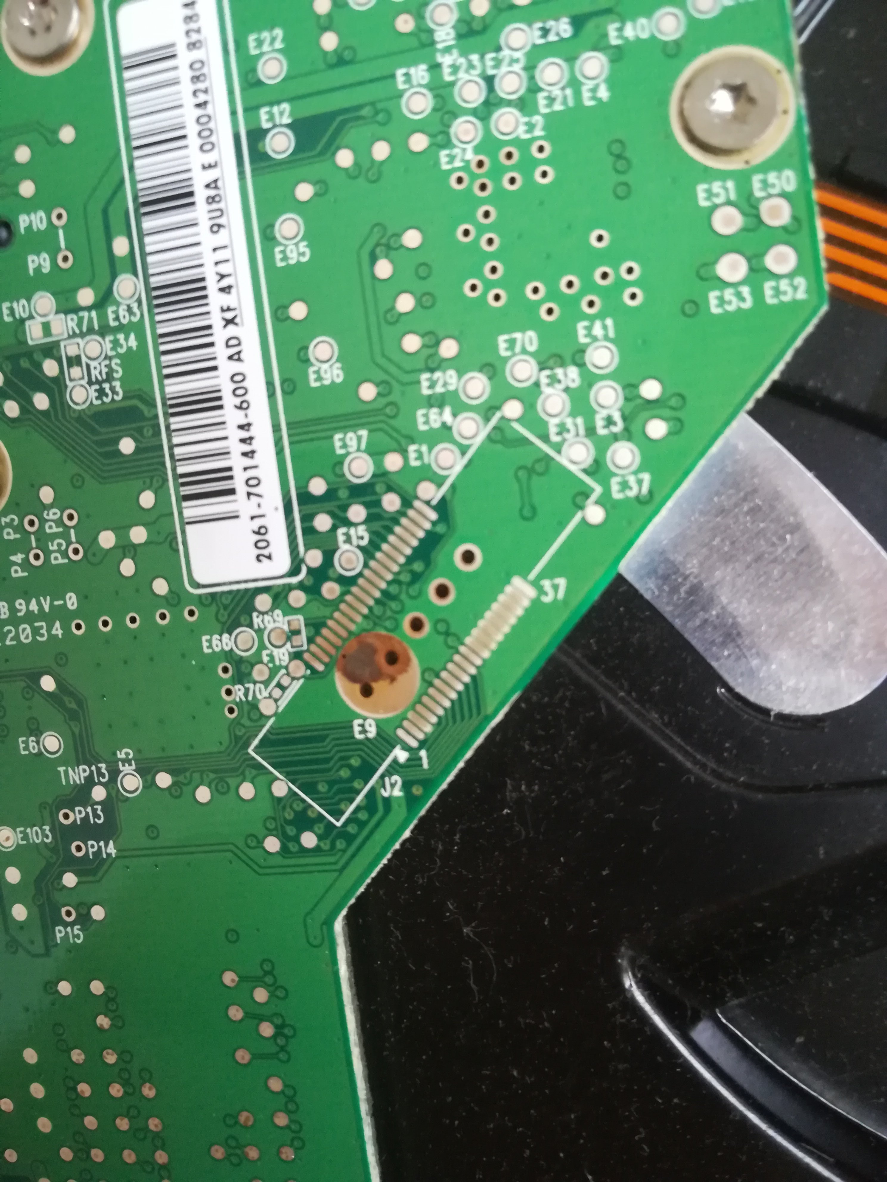
Wanna reuse some old HDDs in the new PC as misc storage and I saw this on a really old drive (the PC it was pulled out of was built in I think 2008/9). Could the discoloration on E9 be because a capacitor leaked? The discoloration seems (from this side at least) to be fully contained on the circle and off of the rest of the PCB

65


I used to play around with 8051 variants and 8pin/16pin PICs back in 2010, whats the equivalent beginner chips now? I have been out of touch since around 2012, except for pi3/4.

66
67


I’m currently working on a more complex project that uses double sided assembly (and a weird USB-C connector). To practice these things a little, I ordered some low cost boards to get used to that connector and explore double sided reflow (which seems easier than I expected).

For those who are interested, this is a reference design from framework computer for their expansion card system. It can be programmed with circuitpython or Arduino and utilises a SAMD21 microcontroller.

68
3
submitted 2 years ago* (last edited 2 years ago) by [email protected] to c/[email protected]


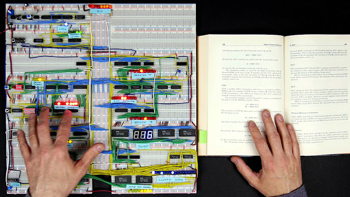
I highly recommend Ben Eater's channel. He's a good teacher, took his time and dedicated months to build quality content in video format, which is a rarity on Youtube these days.

69


I picked this little scope up from the Seapac swap meet a week and a half ago for $3. It turns out that all it needed was some contact cleaner to get it working again.

This is a portable scope that can run from 12V DC as well as an internal battery. I don't have the battery for it, but I could probably put some 18650's in there if I disable the built in charger.

70


Not my video, but a helpful one. If anyone has a lead on a starter oscilloscope, please let me know.

71
0
Ah, there you are! (discuss.tchncs.de)
submitted 2 years ago* (last edited 2 years ago) by [email protected] to c/[email protected]


I saw a few faces peering in the windows of r/electronics as I drove out of the car park having just locked up to head over here. Glad you found your way over.

72
3
Welcome to Electronics (discuss.tchncs.de)
submitted 2 years ago* (last edited 2 years ago) by [email protected] to c/[email protected]


This Lemmy community is an alternative to the Reddit /r/Electronics